Difference between revisions of "Advanced SPACE optimisation and SPACE optimisation+"
(Created page with "=Advanced SPACE optimisation and SPACE optimisation+ set-up= SPACE optimisation and SPACE optimisation + will produce very accurate models of the low frequency interaction betwee…") |
|||
| Line 1: | Line 1: | ||
| − | =Advanced SPACE optimisation and SPACE optimisation+ set-up | + | __FORCETOC__ |
| − | SPACE optimisation and SPACE optimisation + will produce very accurate models of the low frequency interaction between the loudspeakers, room and listening position in a regular rectangular shaped room. There are often cases, however, where some adjustment of the predicted room mode solution is required. For example, if the room does not closely conform to a rectangular floorplan the mode estimates are likely to be in error. Also if the method of construction does not closely match the options provided in Konfig the amount of cut applied for room modes may be in error.<br> | + | <font size=4>Advanced SPACE optimisation and SPACE optimisation+ set-up</font><br> |
| − | + | SPACE optimisation and SPACE optimisation + will produce very accurate models of the low frequency interaction between the loudspeakers, room and listening position in a regular rectangular shaped room. There are often cases, however, where some adjustment of the predicted room mode solution is required. For example, if the room does not closely conform to a rectangular floorplan the mode estimates are likely to be in error. Also if the method of construction does not closely match the options provided in Konfig the amount of cut applied for room modes may be in error.<br><br> | |
| − | |||
| − | Guidelines for simplifying non-rectangular room layouts to better fit to the idealised model are presented in section 3. Additional filters are available in SPACE optimisation and SPACE optimisation + which may also prove useful in some applications. These include bass and treble shelving filters, and user defined custom filters. Examples are given where these filters could be of benefit in odd shaped rooms.<br> | + | This advanced set-up guide presents further information about the calculation and manipulation of [[Advanced_SPACE_optimisation_and_SPACE_optimisation%2B#Room_Modes|section 1]] <br> |
| + | |||
| + | The correct methodology for adjusting the room mode optimisation filters is presented in [[Advanced_SPACE_optimisation_and_SPACE_optimisation%2B#Improving_the_estimated_room_mode_optimisation_using_tune-dem|section 2]]<br> | ||
| + | |||
| + | Guidelines for simplifying non-rectangular room layouts to better fit to the idealised model are presented in [[Advanced_SPACE_optimisation_and_SPACE_optimisation%2B#Simplifying_room_dimensions|section 3]]. Additional filters are available in SPACE optimisation and SPACE optimisation + which may also prove useful in some applications. These include bass and treble shelving filters, and user defined custom filters. Examples are given where these filters could be of benefit in odd shaped rooms.<br> | ||
=Room Modes= | =Room Modes= | ||
Revision as of 08:01, 5 May 2015
Advanced SPACE optimisation and SPACE optimisation+ set-up
SPACE optimisation and SPACE optimisation + will produce very accurate models of the low frequency interaction between the loudspeakers, room and listening position in a regular rectangular shaped room. There are often cases, however, where some adjustment of the predicted room mode solution is required. For example, if the room does not closely conform to a rectangular floorplan the mode estimates are likely to be in error. Also if the method of construction does not closely match the options provided in Konfig the amount of cut applied for room modes may be in error.
This advanced set-up guide presents further information about the calculation and manipulation of section 1
The correct methodology for adjusting the room mode optimisation filters is presented in section 2
Guidelines for simplifying non-rectangular room layouts to better fit to the idealised model are presented in section 3. Additional filters are available in SPACE optimisation and SPACE optimisation + which may also prove useful in some applications. These include bass and treble shelving filters, and user defined custom filters. Examples are given where these filters could be of benefit in odd shaped rooms.
Contents
Room Modes
Konfig provides information which will benefit an experienced installer and allow him to more quickly identify which mode filters will need to be adjusted, and in what way. To make use of this information it is useful to understand the limitations of the Konfig room mode calculation resulting from the assumptions made by the algorithms.
Presented in this section are the fundamental assumptions employed by the room mode optimisation algorithms. Also recommendations for when to adjust the room mode filter centre frequency and bandwidth are presented.
Basic assumptions used for calculations of room modes
The optimisation algorithm assumes that the room is of essentially rectangular layout. This is often not the case. For Konfig to provide a meaningful room mode optimisation more complicated room shapes must be simplified to approximate rectangular dimensions. How the room is simplified will dictate the adjustment required to the Konfig optimisation.
All reflections at room boundaries are considered to be specular. This implies that the reflective characteristics are ideal and are the same at all frequencies. Most real surfaces do not provide specular reflections, instead the magnitude and phase response of any reflected wave is dependent on the incident angle of the acoustic wave. This has significant implications for any non-axial mode (a mode which operates between more than two parallel surfaces).
Adjustment of room modes in Konfig
When a room mode filter is selected from the drop down list the user is provided with the full specification of the parametric equalising filter applied to optimise for the room mode. Any one of the three parameters (centre frequency, gain and bandwidth) may be adjusted to better optimise for a given room mode.
The user is permitted to vary the filter gain by ± 100%, the centre frequency by ± 2 Hz and the bandwidth of the filter by ± 10%.
Additional information provided by Konfig
Konfig provides dimensional information about the room modes. The room mode filter titles shown on the drop down list also include a bracketed set of three characters. This describes the axis of the room along which the standing waves of the room mode occur. Modes active along the length axis of the room are shown as [L--], those active across the width or height are shown as [-W-] and [--H] respectively. The mode descriptor will also inform the installer whether a mode is a simple axial mode (operating along a single room dimension) or if the mode is tangential or oblique (operating between four or six room surfaces).
This is very useful information for the experienced installer. A length mode will be controlled by the characteristics of the front and rear walls. Say, for example, the room has a pitched roof; any height mode will need to be adjusted.
Due to the non-ideal reflective characteristics of real surfaces any non-axial mode is likely to be over-optimised by Konfig. The installer will know that any mode described by more than one letter (e.g. [L-H] or [LW-]) is likely to require adjustment, typically an increase in filter gain (less cut).
Improving the estimated room mode optimisation using tune-dem
Due to assumptions made in the room mode algorithms there will be scope for further optimisation of the filters applied by SPACE optimisation. The process that should be adopted is detailed below.
Open Konfig and go to the SPACE optimisation tab. On the right side of the screen you will see a drop down box listing the room mode optimisation filters, bass and treble shelves and custom filters. A large room will have more optimisation filters than a small room. Selecting an individual optimisation filter allows you to modify the centre frequency of the filter, its bandwidth and its gain.
Room mode filter validity.
- As a first step it is recommended that the installer check the validity of each room mode filter. Filter redundancy may occur if a room surface is particularly irregular, for example a pitched roof. In this instance no strong standing waves will occur between the floor and ceiling and unnecessary optimisation filters may be produced.
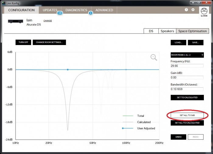
- Once the optimisation has been performed and the graph of all room modes is showing click on the ‘SET ALL TO 0dB’' button.
Using the tune-dem listen to a piece of music, ideally with an even melodic bass line, a couple of times to familiarise yourself with the music.
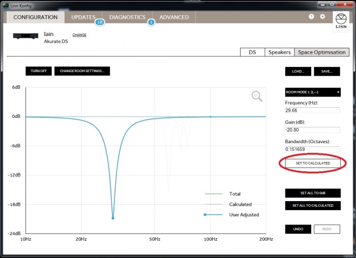
Select room mode 1 from the drop down list on the right. Click on the ‘SET TO CALCULATED’ button.
Listen to the piece of music again. Is it more musical with the mode filter set? If the filter has improved the musicality of the system then move on to room mode filter 2. If the system musicality is no better, or has got worse, then set the room mode filter back to 0dB.
Using the tune-dem re-instate each filter in turn, always starting with the lowest frequency, and ensure that each optimisation filter improves the musicality of the system. If re-instating a filter has no audible effect then return the filter’s gain to zero and move to the next filter.
Adjusting room mode filters for best sonic performance
Once all required room mode optimisation filters have been established some further optimisation may be achieved by altering the gain of the room mode filters (examples of when to adjust frequency and bandwidth are covered in section 2).
Use a piece of music with an even, melodic bass line. Starting with the lowest frequency room mode filter, increase the gain by 6dB (towards 0 dB) and listen again. Using tune-dem decide if the result is an improvement. If the base line sounds more even, try increasing the gain again. If the bass line sounds less even, then reduce the gain. Increase and decrease the gain in progressively smaller steps until the best result is achieved.
Move on to the next valid room mode and repeat.
Always start with the lowest frequency room mode filter. Low frequencies mask higher frequencies so it will be easier to judge the accuracy of the higher frequency mode filters if the lower frequency filters are correct.
Simplifying room dimensions
The room optimisation algorithm in SPACE optimisation is based on the assumption of a largely rectangular room. If the room is slightly non-rectangular (e.g. it has a chimney breast or a bay window) you must decide upon the pertinent dimensions. In general the room dimension should be taken as the distance corresponding to the largest surface area on any given wall. Taking the examples cited above; in the case of the bay window, if the window covers more than half of the wall then measure into the bay window. For the case of the chimney breast, if the chimney covers less than half of the wall surface then measure to the wall either side of the chimney.
If a room is rectangular but has one corner taken up by a partitioned corridor or small anteroom then the larger dimensions should be used.
Simplifying a room to rectangular dimensions
Presented below are some examples of non-ideal rooms and how they should be simplified to fit the rectangular model employed by Konfig. In addition some recommendations are given for each room likely to improve the optimisation produced by the simplified rectangular model.
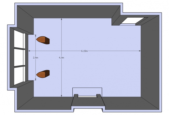
Example room 1, chimney breast and bay window.
In general when measuring a room the dimension should be taken which corresponds to the largest parallel surface area of opposite walls. In the example above, the inset door and chimney breast (fireplace) account for less than 50% of the side walls so they are ignored and the measurement taken is to the most distant surfaces (4.3m). The bay window covers more than 50% of the end wall so the length of the room is measured into the window (6.15m).
As the bay window along with the remainder of the front wall forms a staggered surface some smearing of room modes relating to the length of the room may occur. This can be countered by slightly increasing the bandwidth of any length modes.
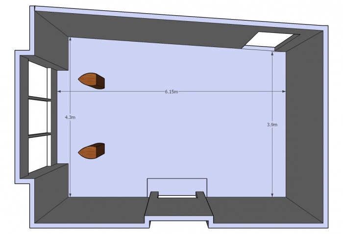
Example room 2, room with one angled wall
Where walls are angled it is recommended to take an average measurement. For the room below the length remains at 6.15, measured into the bay window. The width would be taken as 4.1m, the average width.
Modes relating to the width of the room will need further attention. It is likely that the optimisation filter gain for width modes will need to be reduced as non-parallel walls will reduce the strength of any modal behaviour. It may also be beneficial to increase the bandwidth of any width modes to capture the spread of modal frequencies resulting from the non-parallel surfaces.
Example room 3, room with pitched roof
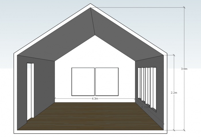
For a room with a pitched roof careful attention to any room modes operating in the vertical axis is required. The most reliable approach for optimising room modes where a pitched roof is present is to take the height measurement to approximately one third of the way up the pitched roof. Run through the modal validity checks (detailed in section 2.1.) to ensure that any calculated height modes are providing benefit. If benefit is found the calculated mode filter may be improved by increasing the bandwidth (5% to 10%) and gain (less cut).
For the example room below this corresponds to a height of 2.7m, an increase in bandwidth of any height modes of between 5% and 10%.
- As the floor plan of the room is a pure rectangle the width and length of the room are as given (4.3m and 6.15m).
Approach for rooms which may not be simplified
In many cases the floorplan of a room may be too complicated to reduce to a simplified rectangular shape. Often, if the room is highly irregular, this may not be too much of a problem as there will be few parallel surfaces between which strong room modes will occur. In other cases where parallel surfaces are evident but the room is impractical to simplify the use of custom filters may prove useful.
This section introduces several such spaces and provides guidance on how to tackle the room mode solution through both the room mode optimisation algorithm as well as the application of custom filters.
Example room 4, L-shaped
A more challenging room shape to configure for room mode optimisation is an L-shaped room. The approach adopted will often depend on the location of the loudspeakers and listening position within the room.
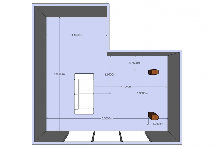
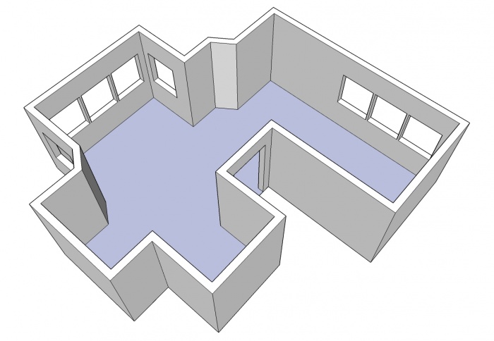
The layout presented below presents quite a dilemma with regard to simplifying the room to a rectangular form. In this case the L-shape splits the room in half along the longest dimension. This makes it impossible to apply the approach where a dimension is dictated by the largest parallel surface of opposite walls (remember the bay window example). If the L-shape had split the room off-centre the choice of room dimensions would be simplified.
Taking the layout presented below, depending on the location of the loudspeakers and listening position there exist three sets of dimensions which could be appropriate for specifying the room in Konfig, namely; 6.3m by 5.9m, 3.9m by 6.3m, or 3.15m by 5.9m.
It may be that the best solution to the problem would be a combination of the mode solutions from two of these possible sets of dimensions. This was a principle reason for the addition of custom filters in SPACE optimisation.
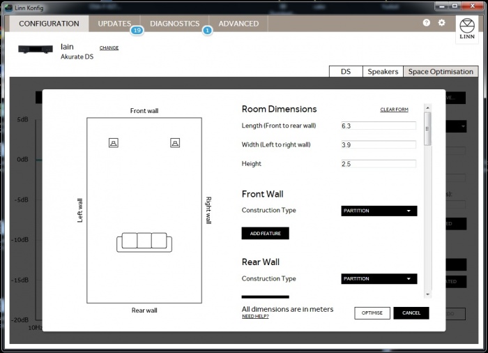
- For example, the loudspeakers are placed on the right side across the 3.9m width firing along the 6.3m length of the room. The initial rectangular layout would have a length of 6.3m and a width of 3.9m.
Let us set the listening position at 4.3m from the front wall, central with regard to the loudspeakers. The loudspeakers, a pair of Akubariks, are placed 1m from the front wall and 0.75m from the side walls.
The room mode algorithm predicts the following four modes:
Calculated Mode
Frequency (Hz)
Gain (dB)
Bandwidth (Oct)
Room Mode 1 [L--] 27.30 -21.83 0.189242 Room Mode 2 [L--] 54.60 -10.72 0.094672 Room Mode 3 [--H] 68.80 -6.26 0.075141 Room Mode 4 [L-H] 74.02 -7.06 0.069844
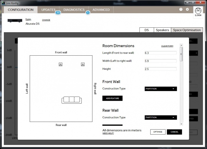
Following the tune-dem process outlined in section 2 all modes are found to be valid but the room still sounds modal. A second model is then produced extending the left wall to the full extent of the l-shaped room. The rectangular layout now has a length of 6.3m and a width of 5.9m. The listening position and left hand speaker move 2m further from the left wall.
Konfig now presents 3 modes:
Calculated Mode
Frequency (Hz)
Gain (dB)
Bandwidth (Oct)
Room Mode 1 [L--] 27.30 -18.10 0.169252 Room Mode 2 [LW-] 39.94 -6.75 0.115729 Room Mode 3 [--H] 54.60 -8.02 0.084663
It is evident that modes 1 and 3 are common to both models, but an additional mode relating to the width of the room has been discovered in the second model. This mode could be added to the original model as a custom filter. It should also be noted that the two common mode filters show reduced gain and increased bandwidth in the second model. This is due to the increase in absorptive surface area and increased room volume in the second room model.
Combining the two models, with an average taken of the two common mode gains and bandwidths we arrive at a better overall solution than either of the two models produced within Konfig. The final mode table now reads;
Calculated Mode
Frequency (Hz)
Gain (dB)
Bandwidth (Oct)
Room Mode 1 [L--] 27.30 19.97 0.179247 Room Mode 2 [L--] 54.60 -9.37 0.089668 Room Mode 3 [--H] 68.80 -6.26 0.075141 Room Mode 4 [L-H] 74.02 -7.06 0.069844 Custom Filter 1 39.94 -6.75 0.115729
As always, final adjustment of the filter gains should be conducted following the process presented in section 2.
Example rooms 5, 6 and 7, non-modal rooms
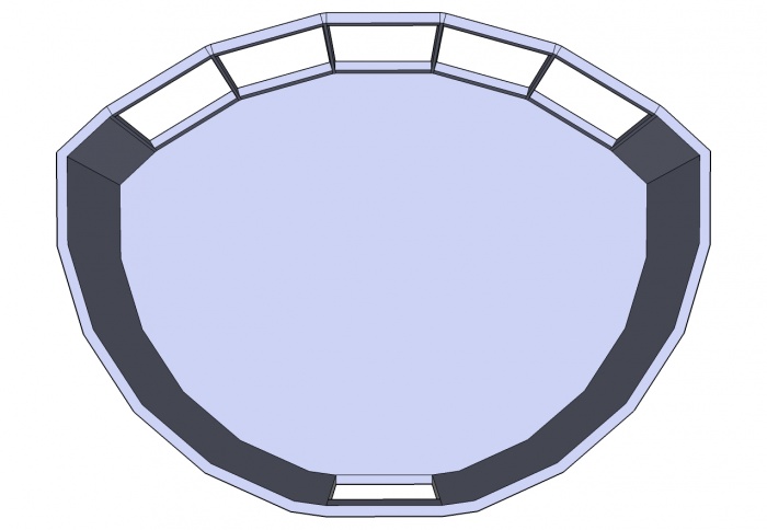
A room mode is set up when a sound-wave whose half-wavelength coincides with the distance between parallel walls. As a result, rooms of highly irregular floorplan, those with significant curved walls or those with predominantly non-parallel surfaces will often exhibit very few room modes.
In such cases it is necessary to identify any large parallel surfaces in the room (often the floor and ceiling) and target the room model to focus on these surfaces.
In the two room examples above it is highly unlikely that any room modes relating to the length or width of the room will dominate the soundfield at the lisetning position. But both cases, assuming the floor and ceiling are parallel may exhibit hight modes. In such cases it is useful to describe the room with an arbitrary floorplan large enough to encompass the loudspeakers and listening position, but to accurately specify the ceiling height.
When Konfig produces its room mode optimisation filter estimate set all mode filters to zero gain, except the height modes (those with the suffix [--H]). Use the tune dem approach detailed in section 2.1 to assess the validity of the height modes.
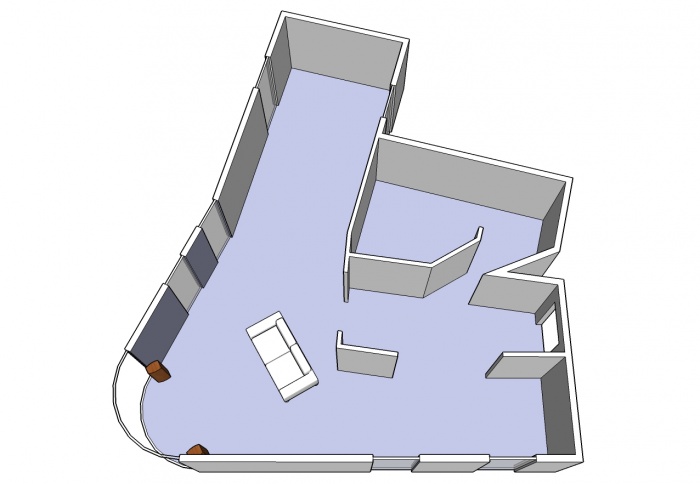
The final example room, one with essentially non-parallel walls should be treated in the same way as the curved wall and irregular floorplan rooms. Two additional features of this example installation mat benefit from the application of custom filters.
The first likely issue is the anteroom adjoining the listening space with an open doorway. This may exhibit a resonance separate from the principle listening space. Little can be done to model this room and its impact on the room mode solution, but a custom filter may be applied to reduce its impact on the performance of the system. Setting the custom filter could be done by analysing the anteroom issue with a third party measurement acoustic system, though it is likely that a good result could be found tuning the filter by ear. Set the custom filter a reasonably wide bandwidth and a gain of -10 dB, adjust the frequency until the impact of the anteroom resonance on the music is reduced. Now the filter is roughly centred apply the tune-dem to gradually fine tune the bandwidth, gain and frequency.
A second likely problem with the installation is the close proximity of the speakers to the sidewalls. This may well result in excess boundary support in the upper bass and lower midrange. Placement optimisation is designed to function when the loudspeaker is bounded by two perpendicular planes, in other words the speaker should be located near the corner of a room. In the example above neither speaker is located in a true corner so placement optimisation will be unable to accurately resolve the tonal issues due to this loudspeaker placement. A custom filter should be applied. Set the frequency to lie in the problem range, around 140 Hz. Give the filter a wide bandwidth, ~ 3 octaves and a gentle cut of about 2dB. Use the Tune-dem to adjust the filter.
Bass and Treble shelves
An additional pair of filters is available in SPACE optimisation and SPACE optimisation +, namely the bass and treble shelves. These may be considered as a highly flexible and customisable equivalent to a classic tone control.
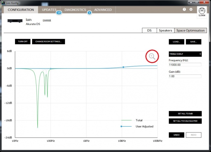
The treble shelf can be varied between + 2dB and -2dB with a corner frequency between 8 kHz and 12 kHz. For rooms with a large amount of soft furnishings, or for installations where the listening position is further from the loudspeakers than is typical the high frequency shelf can be employed to add lift to the treble. Conversely if the room contains mainly hard reflective surfaces some cut may be required to calm to top end of the music spectrum. When applying a treble shelf ensure you click on the magnifying glass symbol on the plot area to ensure you get a visual representation of the filter being applied.
The low frequency shelf can apply cut or boost to low frequencies with a corner between 20Hz and 200Hz. The limits of cut and boost are specific to each model of speaker but typically cover the range -6dB to + 3dB. It is generally advisable when applying boost to set the corner frequency at 65Hz or lower to avoid disrupting the vocal presentation of the system.
Both treble and bass shelves are user configurable and the tune-dem should be utilised when making adjustments.
Importing and exporting settings
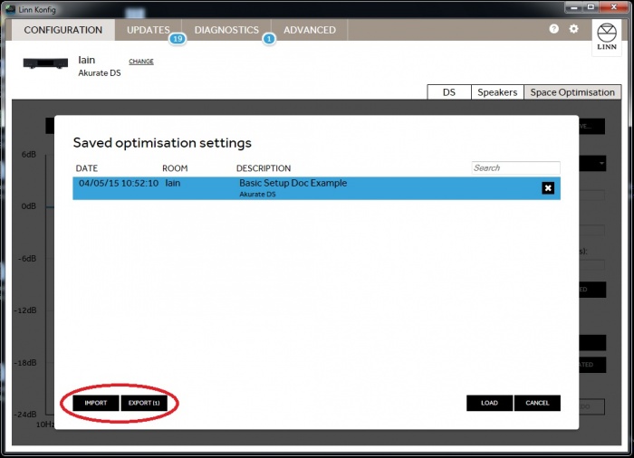
It may be desirable to safeguard you finalised optimisation set-up by storing the saved files in a separate location. Konfig provides the capability to import or export saved setup files.
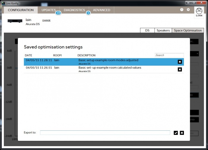
Within the load setup page on the Konfig optimisation page there are two buttons; ‘IMPORT’ and ‘EXPORT’, these can be used to back-up any saved optimisation set-up files.
Clicking on either ‘IMPORT’ or ‘EXPORT’, you will be presented with a textbox into which you must enter the full directory location for any setup files you wish to import or export.
