Difference between revisions of "Up-sampling"
(New page: === Up-sampling === All Linn DS products share the same custom-designed up-sampling engine, implemented in a Xilinx Virtex-4 FPGA. The up-sampler takes digital audio at any of the support...) |
m |
||
| (9 intermediate revisions by 3 users not shown) | |||
| Line 1: | Line 1: | ||
| − | + | {{:Linn_Feature}} All Linn DS products share the same custom-designed up-sampling engine, implemented in a Xilinx Virtex-4 FPGA. The up-sampler takes digital audio at any of the supported sample rates and up-samples it to a constant rate. Linn products with the Wolfson DAC this is 352.8kHz or 384kHz, and for the Katalyst DAC this is 705.6kHz or 768kHz. This allows the up-sampling filters in the third party DAC to be bypassed, thus removing a potential source of noise and signal distortion. | |
| − | |||
| − | All Linn DS products share the same custom-designed up-sampling engine, implemented in a Xilinx Virtex-4 FPGA. The up-sampler takes digital audio at any of the supported sample rates and up-samples it to a constant rate | ||
| − | |||
The filter shapes used in the Linn DS up-sampler are the result of extensive listening tests. Various filter shapes were tried including linear-phase, minimum-phase, apodizing, etc. The resulting filter has a linear-phase characteristic and is what Linn term a ‘true’ upsampling filter. This means that it is fully attenuating at the Nyquist frequency and so prevents the formation of ultrasonic-images | The filter shapes used in the Linn DS up-sampler are the result of extensive listening tests. Various filter shapes were tried including linear-phase, minimum-phase, apodizing, etc. The resulting filter has a linear-phase characteristic and is what Linn term a ‘true’ upsampling filter. This means that it is fully attenuating at the Nyquist frequency and so prevents the formation of ultrasonic-images | ||
| + | Most up-sampler designs use ‘half-band’ filters because they are computationally more efficient than other filter types. The disadvantage of the half-band filter in an upsampling application is that it only attenuates by -6dB at the Nyquist frequency. This results in the upper portion of the audio band being ‘reflected’ around the Nyquist frequency. | ||
| − | . | + | Implementing a ‘true’ upsampling filter requires significant processing power if parameters such as pass-band width, pass-band ripple, and stop-band attenuation are not to be compromised. Implementing the design in an FPGA allows complete control of the digital signal path and allows high-performance filters to be implemented with high mathematical precision. |
| − | + | <br> | |
| − | + | [[Image:Up-sampling filter diag.png|center]] | |
Latest revision as of 13:22, 24 July 2023
All Linn DS products share the same custom-designed up-sampling engine, implemented in a Xilinx Virtex-4 FPGA. The up-sampler takes digital audio at any of the supported sample rates and up-samples it to a constant rate. Linn products with the Wolfson DAC this is 352.8kHz or 384kHz, and for the Katalyst DAC this is 705.6kHz or 768kHz. This allows the up-sampling filters in the third party DAC to be bypassed, thus removing a potential source of noise and signal distortion.
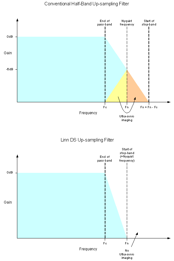
The filter shapes used in the Linn DS up-sampler are the result of extensive listening tests. Various filter shapes were tried including linear-phase, minimum-phase, apodizing, etc. The resulting filter has a linear-phase characteristic and is what Linn term a ‘true’ upsampling filter. This means that it is fully attenuating at the Nyquist frequency and so prevents the formation of ultrasonic-images
Most up-sampler designs use ‘half-band’ filters because they are computationally more efficient than other filter types. The disadvantage of the half-band filter in an upsampling application is that it only attenuates by -6dB at the Nyquist frequency. This results in the upper portion of the audio band being ‘reflected’ around the Nyquist frequency.
Implementing a ‘true’ upsampling filter requires significant processing power if parameters such as pass-band width, pass-band ripple, and stop-band attenuation are not to be compromised. Implementing the design in an FPGA allows complete control of the digital signal path and allows high-performance filters to be implemented with high mathematical precision.
