Up-sampling
All Linn DS products share the same custom-designed up-sampling engine, implemented in a Xilinx Virtex-4 FPGA. The up-sampler takes digital audio at any of the supported sample rates and up-samples it to a constant rate of 352.8kHz or 384kHz. This allows the up-sampling filters in the third party DAC to be bypassed, thus removing a potential source of noise and signal distortion.
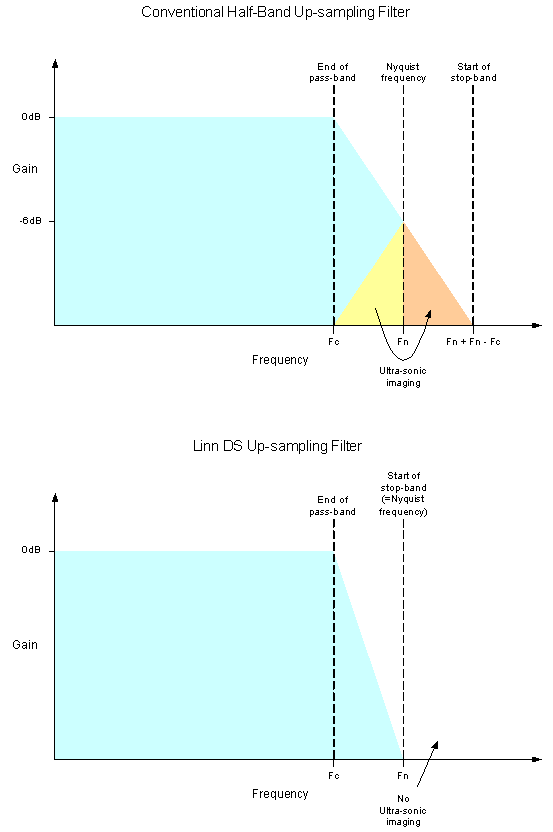
The filter shapes used in the Linn DS up-sampler are the result of extensive listening tests. Various filter shapes were tried including linear-phase, minimum-phase, apodizing, etc. The resulting filter has a linear-phase characteristic and is what Linn term a ‘true’ upsampling filter. This means that it is fully attenuating at the Nyquist frequency and so prevents the formation of ultrasonic-images
Most up-sampler designs use ‘half-band’ filters because they are computationally more efficient than other filter types. The disadvantage of the half-band filter in an upsampling application is that it only attenuates by -6dB at the Nyquist frequency. This results in the upper portion of the audio band being ‘reflected’ around the Nyquist frequency.
Implementing a ‘true’ upsampling filter requires significant processing power if parameters such as pass-band width, pass-band ripple, and stop-band attenuation are not to be compromised. Implementing the design in an FPGA allows complete control of the digital signal path and allows high performance filters to be implemented with high mathematical precision.
